Activity 1 Part (c): Control of a Resistor–Capacitor (RC) Circuit

Key Topics: Model-Based Design, Root Locus, PI Control, Steady-state Error, Analog Control
Contents
Equipment needed
- Arduino board (e.g. Uno, Mega 2560, etc.)
- Breadboard
- Push-button switch
- Electronic components (resistors and capacitors)
- 3 Potentiometers (10k, 50k, 500k)
- 3 Operational amplifiers
- Alkaline batteries (one AA, two 9-V)
- Jumper wires
This activity follows the modeling and identification activities explored in Activity 1a and Activity 1b. We will employ the same Resistor–Capacitor (RC) Circuit as employed in the previous portions of the experiment, except now we will implement control to alter the dynamics of the system. The control law will be implemented in hardware, as opposed to other activities where the control law is implemented in software. The Arduino board will only be employed for reading the voltage across the output capacitor, via one of the board's Analog Inputs. This data is then fed to Simulink for visualization.
Purpose
The purpose of this activity is to demonstrate how to design a controller in order to modify a system's dynamic response. In particular, how to employ a system's root locus to help tune a feedback controller in the presence of uncertainties in the model is demonstrated. This activity also demonstrates how to implement a control law using analog electronics.
Control requirements
Consider our plant to be the same RC circuit that we have been examining, shown below. In this example, we employ the following
variables where  will be the control input to the plant and
  will be the output that we ultimately wish to control.
(R) resistance of the resistor
(C) capacitance of the capacitor
(ei) input voltage
(eo) output voltage

From Activity 1a, we derived a theoretical model for the RC circuit plant that has the form of a standard first-order system.
(1)
From inspection, we can see that speed of response of the system is determined by the circuit components  and
and  . Specifically, since the the circuit's time constant is
  , the 2
  settling time for the system is
  . Furthermore, the steady-state gain of the circuit is always equal to 1, no matter the choice of components.
If we wished to change the circuit's speed of response, one solution would be to modify the circuit's components  and
and  . A challenge would be that if the conditions under which the circuit operated changed, then the circuit would again not provide
the desired behavior. For example, if the circuit components aged, or if there were some unmodeled effects from the measurement
channel, or some exogenous noise or disturbance inputs added to the system, then the output would not match what was designed
for. One solution to modify the system's behavior such that its performance is robust to these effects, and such that the
physical plant does not need to be modified, is to add a feedback controller to the system.
In this activity, we will specifically design a Proportional-Integral (PI) feedback control system of the form shown below.

We will consider an RC circuit with the same component values as employed in the previous portions of this activity. Since
 and
and  , our uncompensated plant has a 2
  settling time of approximately
  seconds. Therefore, we will attempt to increase our system's speed of response to a step change in requested voltage, while
not exhibiting too much overshoot. In consideration of the hardware-based implementation of our control law that will ultimately
be employed (details below), we will also attempt to keep the control effort (
 ) below 7 Volts. Also note that since the PI controller makes our system Type 1, it will track a step reference with zero
steady-state error. The specific controller requirements that we will design for are given below.
- 2
 settling time less than 1 second
- Peak time less than 0.350 seconds
- Maximum overshoot less than 25

- Maximum control effort less than 7 Volts
Controller design via algebraic pole placement
In this section, we will initially design our PI controller algebraically. That is, we will choose the control gains  and
and  to place the closed-loop poles in some desired locations. Therefore, we must first determine the closed-loop transfer function
for the system as defined above.
(2)
By inspection, we see that the closed-loop system is second-order with a zero. The system does not match the canonical form shown below because of the presence of the zero.
(3)
Despite the presence of the zero, we will initially treat our system as if it did have a canonical form. Therefore, our initial design will not reflect the true behavior of our closed-loop system with zero. However, this design will provide a good starting point and will prove qualitatively helpful to us in the tuning of our controller.
Matching the denominator of our closed-loop transfer function  to the canonical form above, we get the following relationship between control gains and desired closed-loop pole locations
(as indicated by
  ,
,  , etc.).
(4)
(5)
We can then choose our control gains in an attempt to achieve closed-loop pole locations that satisfy our original system requirements on settling time, peak time, and maximum overshoot. In this process we will use the following expressions, which again assume a canonical second-order underdamped system (which we don't have).
- 2
 settling time:
- Peak time:

- Maximum percent overshoot:

Based on the given requirements and assumed relationships shown above, we can determine the desired poles locations that in
turn determine our choice of control gains  and
and  . In order to satisfy our settling time requirement, we place the following constraint on
  .
.
(6)
Now examining our peak time requirement, we determine a constraint on  .
.
(7)
And finally, our maximum percent overshoot requirement places a constraint on  .
.
(8)
If we choose our gains to meet the three above constraints, our closed-loop system will not be guaranteed to meet the associated requirements because our system is not canonical (it has a zero), not to mention that the actual physical plant won't exactly match our theoretical model. That being said, the above relationships are useful qualitatively in guiding the tuning of the control gains as we will eventually demonstrate.
To help visualize the above requirements, we will map them to the complex s-plane as shown below. Specifically,  corresponds to the real part of our poles,
  corresponds to the imaginary part of our poles, and
  maps to the angle
  via the relation
  . Therefore, we need
  . The shaded region corresponds to the pole locations that satisfy all three requirements.
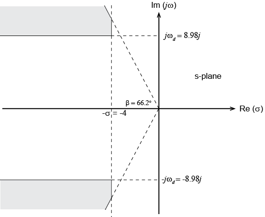
Based on these requirements, we can choose the closed-loop poles to equal  . We could also choose the poles to meet the requirements with greater margin, the only drawback is that making the system
"faster" (smaller settling time and smaller peak time) tends to come at the cost of increased control effort, something we
will discuss when we implement our controller. Now looking back at our original closed-loop transfer function, we can pick
our control gains
  and
and  to achieve the chosen closed-loop pole locations, where
  equals 5 and
  equals 10.
(9)
(10)
Employing these control gains, our theoretical closed-loop transfer function is then the following.
(11)
We already know that the actual system response won't match the response predicted by the expressions derived for a canonical system, but we can use MATLAB to examine just how large of an effect the added zero has. Execute the following code in the MATLAB command window to generate the figure shown below.
s = tf('s');                            % define the Laplace variable s
Kp = 9;                                 % proportional control gain
Ki = 125;                               % integral control gain
T = (Kp*s + Ki)/(s^2 + (1+Kp)*s + Ki)   % theoretical closed-loop transfer function
Canon = Ki/(s^2 + (1+Kp)*s + Ki)        % canonical transfer function with matching
                                        % poles and DC gain
step(T)                                 % theoretical step response
hold
step(Canon,'r--')                       % canonical step response
ylabel('output voltage (Volts)')
title('Closed-loop Step Response')
legend('with zero','without zero')
T =

     9 s + 125
  ----------------
  s^2 + 10 s + 125

Continuous-time transfer function.


Canon =

        125
  ----------------
  s^2 + 10 s + 125

Continuous-time transfer function.

Current plot held
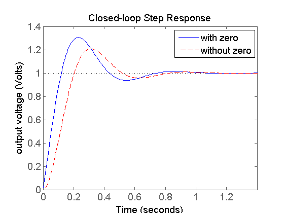
Inspection of the above demonstrates that the presence of the zero results in a faster response and greater overshoot than
predicted by the canonical relations. This effect is typical of a minimum-phase zero (zero in the left-half s-plane). In terms
of our requirements, the peak time is smaller than designed for, so the peak time requirement is met. It also appears that
the settling time requirement is met. The overshoot, however, is greater than was designed for and is greater than the 25
 requirement. This initial set of gains, however, is a good starting point for the tuning of our controller. Furthermore,
these canonical relations will be helpful in tuning our controller, at least in terms of identifying trends. It is necessary
for us to manually tune our control gains, not only because we have a non-canonical system, but also because the real physical
system will not exactly match the plant model we have so far assumed. We will specifically employ a root locus approach to
tuning the physical controller in the subsequent sections of this activity.
Control experiment
Hardware setup
In this experiment our "plant" is the same RC circuit we have employed in the previous portions of the activity ( and
and  ). Now we will add feedback control to our RC circuit. In most of the other activities we have conducted, we have implemented
our control laws in software (Simulink) and have controlled our systems (lightbulb, boost converter, DC motor) via a Digital Output of the Arduino board using pulse-width modulation (PWM). By making the frequency of the PWM signal
sufficiently high, we were able to achieve approximately "continuous" control by varying the duty cycle of the PWM signal.
In this experiment, we will rather implement our control law in hardware using operational amplifiers to achieve truly analog
(continuous) control. The Arduino board will simply be employed for acquiring the output voltage data from the circuit (via
an Analog Input), and for communicating that data to Simulink.
The use of operational amplifiers will allow us to construct what is in essence an analog computer. Configuring an operational amplifier in various ways (with resistors and capacitors) allows us to carry out various mathematical operations on the input signals (addition, subtraction, differentiation, integration, etc.). Our control law will be implemented as follows. The first part of the circuit takes the difference between the reference command and the output, the second part of the circuit is an implementation of a PI controller, and the final part of the circuit is our plant.
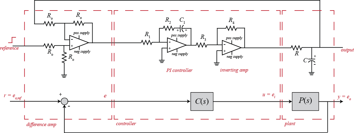
In this experiment, our reference is a unit (1-V) step as supplied by a battery via a push-button switch. In order to scale
the battery voltage to 1 Volt (a AA battery is nominally 1.5 Volts), the reference input is fed through a voltage divider
employing a  potentiometer. Scaling the reference input via the potentiometer allows us to keep a consistent input in the presence of
component variation (i.e. resistance
  , and battery voltage). A 1-V step is also sufficiently small that the required control effort won't be too large.
For the difference amplifier we employ a relatively inexpensive general purpose operational amplifier, the LM741, whose datasheet
can be found here. The difference amplifier is configured as shown (for a dual in-line package (DIP)) with  resistors. Such an operational amplifier will introduce a bias that can be removed by adjusting a trimming potentiometer
between the offset null pins 1 and 5. Since the bias is relatively small (< 6 mV), we will neglect to do this. Power for this
operational amplifier (as well as the others in the circuit) will be supplied by two 9-V batteries (
 9 Volts). One can consider that the two 9-V batteries are in series such that where the positive terminal of one battery
is connected to the negative terminal of the other battery is considered ground (0 Volts). The unconnected positive battery
terminal then corresponds to +9 Volts, and the unconnected negative battery terminal then corresponds to -9 Volts.
The PI compensator will be implemented as shown, employing two operational amplifiers, four resistors, and a capacitor. The
two operational amplifiers are contained in the same 8-pin DIP, the LM358, whose datasheet can be found here. The LM358 is another inexpensive general purpose operational amplifier. Power for the operational amplifiers will be supplied
by the same two 9-V batteries employed with the difference amplifier. The use of the  9-Volt supply limits the amount of control effort
  that can be supplied by this controller. Specifically, we will attempt to tune our controller to require less than approximately
7 Volts while achieving the other given requirements.

The control gains  and
and  are set via the choice of resistor and capacitor values as shown below.
(12)
(13)
In this experiment, we employ fixed components for  ,
,  , and
, and  , and will use potentiometers for
  and
and  , thereby allowing us to tune our control gains. Specifically, we will nominally use
  resistors for
  and
and  , and a
  capacitor for
  . Therefore, in order to set our initial integral gain as calculated,
  , we will set the potentiometer for
  as follows.
(14)
With  set, we will then set the potentiometer for
  to achieve the initial proportional gain we calculated,
  , as shown below.
(15)
In order to account for the uncertainty in our model, as well as its non-canonical nature, we will tune the potentiometers
for  and
and  in the following.
Software setup
In this experiment, we will simply employ Simulink to read the data from the board and to plot the data in real time. In particular, we will employ the IO package from the MathWorks. For details on how to use the IO package, refer to the following link. The Simulink model we will use is shown below and can be downloaded here, where you may need to change the port to which the Arduino board is connected (the port is COM3 in this case). Since the control law is implemented in hardware and the reference is generated via a push-button switch, the Simulink model is very simple and only monitors two signals from the circuit.

One Arduino Analog Read block reads the output voltage data  via the Analog Input A0 on the board. Double-clicking on the block allows us to set the Pin to 0 from the drop-down menu. The other Arduino Analog Read block can be connected to other signals in the circuit. In this case,
the block is reading the reference voltage via Analog Input A1 in order to verify that the reference is indeed a 1-Volt step.
The control input
  is another important signal that we may wish to observe. The only problem is that the input signal will likely exceed the
5-Volt range of the channel. Therefore, if we wished to read this signal, we would need to employ a voltage divider, or another
operational amplifier, to scale the signal to less than a 5-Volt maximum. The Sample Time for the two read blocks is set to "Ts". We set this parameter by typing Ts = 0.01; at the MATLAB command line. The Gain blocks are included to convert the data into units of Volts (by multiplying the data
by 5/1023).
The given Simulink model then plots the commanded reference voltage and recorded output voltage on a scope and also writes the output data to the MATLAB workspace for further analysis. The Arduino Analog Read block, the Arduino IO Setup block, and the Real-Time Pacer block are all part of the IO package. The remaining blocks are part of the standard Simulink library, specifically, they can be found under the Math and Sinks libraries.
Once the potentiometers have been set and the Simulink model has been created, the model can then be run. During the running
of the model, you must press the push-button switch to generate the step reference for the circuit. The potentiometer at the
reference input is set to achieve a reference of 1 Volt, while  is set to
  to achieve
  and
and  is set to
  to achieve
  . The reference voltage and the potentiometer settings can be verified with a multimeter. Our initial set of control gains
achieves the performance shown below.
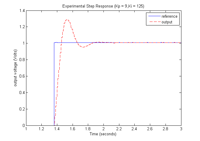
From inspection, we can see that peak time of the step response is approximately 0.17 seconds and the settling time is approximately
0.45 seconds. Both of these characteristics easily meet the given requirements. However, the observed overshoot is approximately
29  , which exceeds the 25
  requirement. Furthermore, the control effort (not shown) for the 1-Volt step referenced exceeds 7 Volts and actually saturates
at approximately 7.3 Volts due to the limited output the operational amplifiers are capable of generating when provided
  9 Volts of supply power. The control effort was measured with alternative equipment because the level of voltage exceeds
the 5-Volt limit that the analog inputs of the Arduino board are capable of sinking. One could use a voltage divider or operational
amplifier to scale the control effort signal so that it may be read by the Arduino board. In such a case, one could deduce
the true control effort based on knowledge of the induced scaling.
The overshoot requirement that was designed for was not met primarily due to the fact that the controller gains were chosen to place the poles according to relationships that only hold for canonical second-order systems. The presence of the zero in the closed-loop transfer function resulted in a higher level of overshoot than designed for. Even in comparison to the theoretical step response for the transfer function with zero, the predicted characteristics don't match the actual experimental response due to variation in circuit component values as compared to the values assumed in the model, as well as due to various unmodeled effects. In the following, we will experimentally tune our controller to meet the given requirements despite the uncertainties in the model and its non-canonical nature.
Controller tuning via the root locus
In order to tune our control gains to better meet the given requirements, we will use the root locus. Recall that the root
locus plots a system's closed-loop poles as a parameter is varied from 0 to infinity. We will, in particular, employ MATLAB's
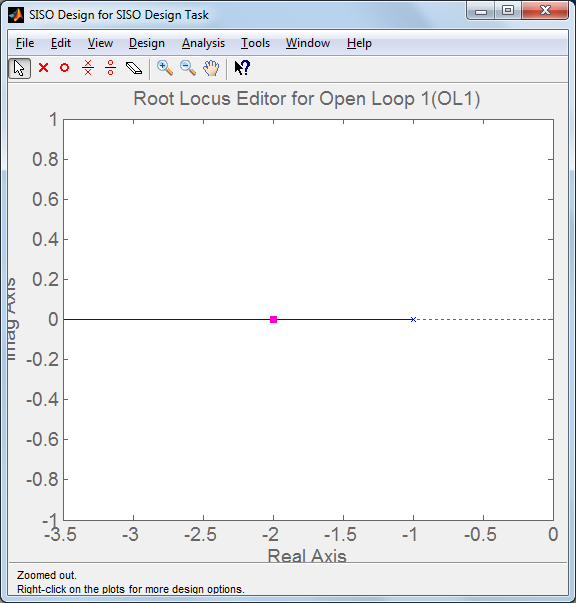
SISO Design Tool graphical user interface. This tool allows you to graphically tune the controller via the root locus plot. Let's first view
the root locus for the uncompensated plant. Recalling that for our choice of  and
and  , our plant has the following transfer function.
(16)
Therefore, we can launch the SISO Design Tool for this plant by entering the following code at the MATLAB command line.
         s = tf('s');
         P = 1/(s+1);
         sisotool('rlocus',P)
Two windows will initially open, one is the SISO Design Task which will open with the root locus of the uncompensated plant as shown below. The other window is Control and Estimation Tool Manager which allows you to design compensators, analyze plots, etc.
Next we will add our initial PI compensator to the root locus. In order to put the compensator in the form expected by the SISO Design Tool, we perform the following manipulation.
(17)
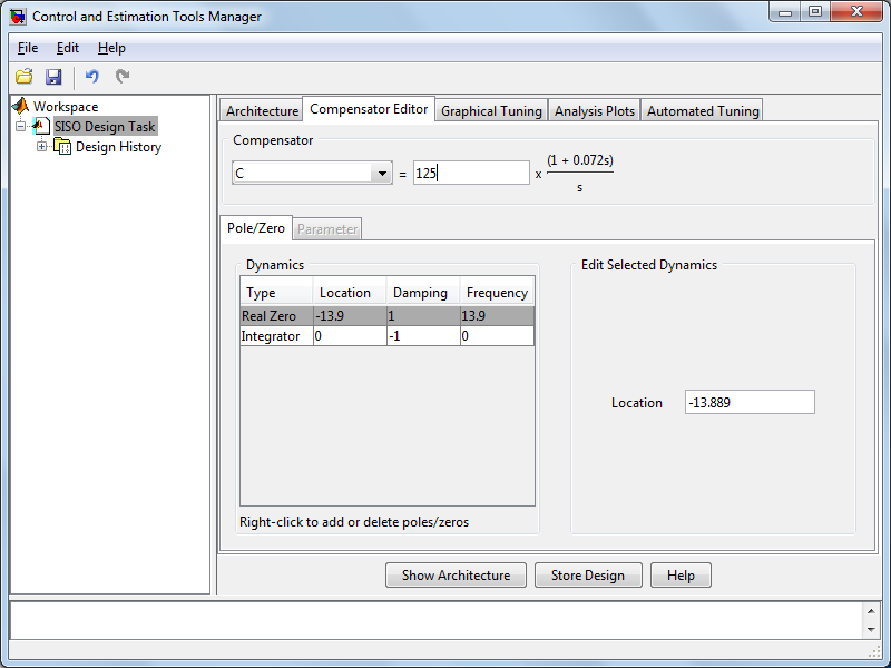
We can then add the PI compensator from under the Compensator Editor tab of the Control and Estimation Tools Manager window. From the above, we can see that the compensator adds a zero and a pole at the origin (an integrator). Therefore, by right-clicking in the Dynamics section of the window we can select Add Pole/Zero > Integrator. We can then right-click in the Dynamics section of the window and select Add Pole/Zero > Real zero. We can then enter -125/9 for the real zero location and can set the loop gain to 125, as shown below.
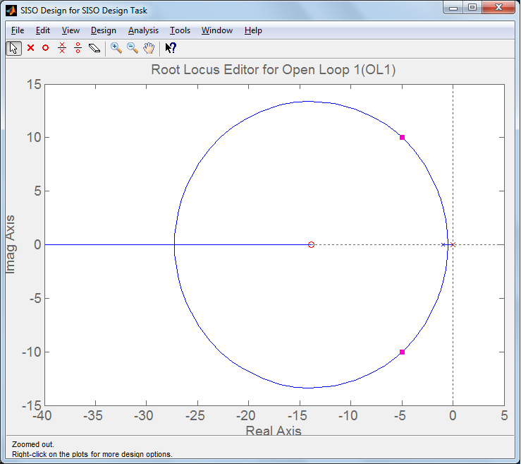
Returning to the window with the root locus, we can see the effect of adding the PI compensator as shown below. The pink squares
mark the closed-loop pole locations ( ) achieved for the current choice of loop gain. For the controller in its current form, the loop gain corresponds to
  and the zero location corresponds to
  .
.
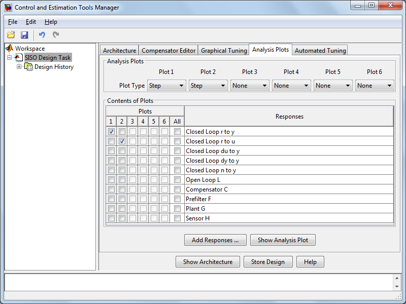
For this controller, we can also inspect the closed-loop system's predicted time response. Specifically, we can plot the unit
step response of the output  . We can also plot the corresponding response of the system's control effort
  . These plots are lauched from under the Analysis Plots tab of the Control and Estimation Tools Manager window as shown below.
The resulting analysis plots will then appear as follows (top plot is the output, bottom plot is the control effort). The closed-loop step response shown should match the step response plot we created from the MATLAB command line earlier (with zero).
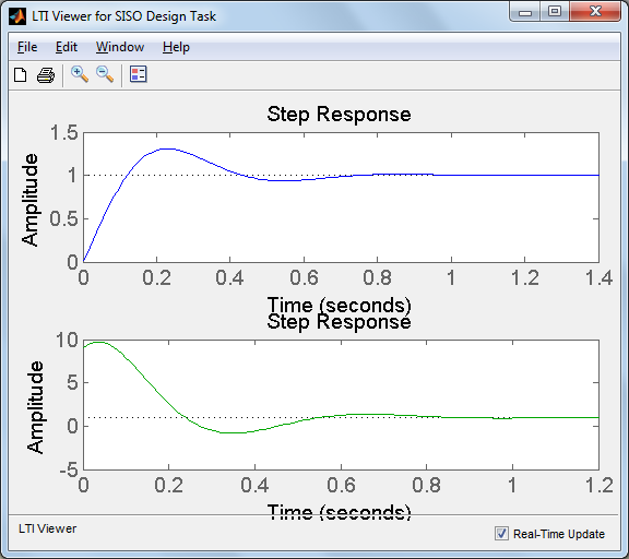
The theoretical output step response shows a level of overshoot that exceeds our requirements as we saw with our actual experimental
data. Furthermore, the predicted control effort exceeds the 7-Volt limit just as our experimental data did. Even though our
theoretical model does not match the experimental data perfectly, and even though it is not a canonical form, we can employ
the root locus plot and the canonical relations for  ,
,  , and
, and  to qualitatively tune our control gains.
For example, since our overshoot is too great, we can move our closed-loop poles in order to decrease the corresponding value
of  . The specific relationship between
  and
and  derived from the canonical second-order form won't hold, but the qualitative prediction that bigger
  results in smaller
  , often will.
In order to decrease the control effort, it often works to "slow" the system response down. If we don't have to get there
quite as fast, we don't have to push quite as hard. Therefore, based on the relationship  , we will attempt to move our closed-loop poles to decrease
  in order to increase
  . The given expression again won't be able to predict the true value of
  , but the relation often will provide a qualitative prediction.
Recalling that the loop gain for this controller corresponds to  and the zero location corresponds to
  , we can use the SISO Design Tool to tune our control gains. Looking at the root locus from above, let's first try to achieve
our tuning goals (decrease
  , decrease
  ) with a simple gain change. Within the Root Locus Editor, clicking on the pink boxes that represent the current closed-loop
pole locations, we can slide the closed-loop poles along the root locus (corresponding to a change in loop gain
  ). Decreasing
  moves the closed-loop poles down and to the right which decreases
  , but also increases
  . If you attempt this, you can see the corresponding increase in
  and increase in
  in the Analysis Plots. Increasing
  slightly achieves the opposite effect. If we increase
  enough that the closed-loop poles move to the other side of the circular portion of the root locus, then both
  and
and  can be decreased. Unfortunately, this level of reduction in overshoot and settling time requires an increase in control effort,
as indicated by the Analysis Plots.
Since the manipulation of the loop gain is not able to meet both of the goals of our tuning, we will additionally have to
move the zero in our root locus. In other words, we will need to use both of our degrees of freedom ( and
and  ) to achieve our control goals. Specifically, moving the zero provided by the controller to the right will decrease the size
of the circular portion of root locus, thereby assisting with the goals of decreasing
  and
and  . By clicking on the zero in the Root Locus Editor, you can graphically tune the zero location (and loop gain) and can see
the resulting effect on the analysis plots in real time.
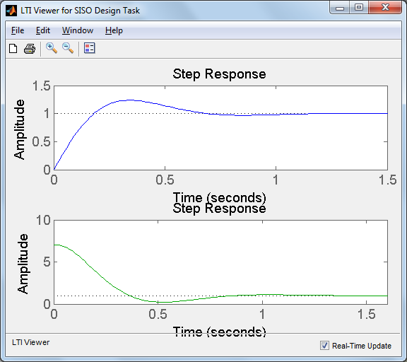
By some trial and error, we arrive at a zero location of -7.7 and a loop gain of 54, which produces the following theoretical predictions for output and control effort. These time graphs demonstrate an overshoot of approximately 24 percent and a control effort of 7 Volts, while still meeting our peak time and settling time requirements.
Of course, we must still verify these results on our actual physical plant due to the limitations of our model. Recall that
for this controller the loop gain corresponds to  and the zero location corresponds to
  . Therefore, control gains of
  and
and  will match the design we just arrived at. The following calculations then demonstrate the resistance values that will provide
these control gains.
(18)
(19)
Adjusting the potentiometers that correspond to  and
and  to the above values and then rerunning the Simulink model generates the response shown below. Don't forget to press the push-button
to generate the step reference.
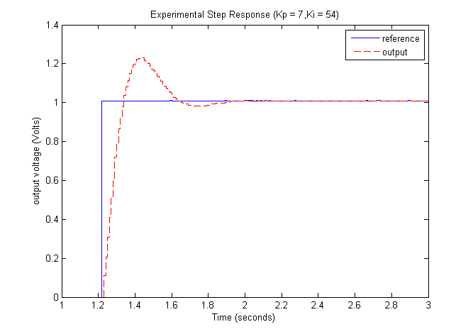
Inspection of this data shows a maximum percent overshoot of approximately 23 percent, a peak time of 0.22 seconds, and a settling time of 0.42 seconds, all while keeping the control effort below 7 Volts. Hence this control law meets the originally prescribed requirements. If this set of control gains had not met our requirements, we could then return to the SISO Design Tool to iterate on our design again using the qualitative insight provided by our model.
Hardware vs. software implementation
In this activity we implemented our control law via analog circuit components, thereby avoiding the necessity of a microcontroller for achieving closed-loop control. In practice, this may be desirable as a means for reducing cost as the circuit components we employed are quit inexpensive.
A disadvantage that you may have noticed is that building the control circuit and tuning the control gains was somewhat tedious. If we had implemented our control law in software, we could change the control gains or even the structure of the controller with just a couple of keystrokes. Furthermore, if we wished to implement some discrete logic in our controller, for example, if we wished to change control gains based on the reference setpoint, it would be much harder to achieve in hardware than it would be to achieve in software.
If a control law is implemented in software, you must be careful to consider the digital nature of the signals. If the sampling times are significant compared to the speed of the system, you may need to employ digital control design techniques. Furthermore, if you aren't able to generate analog control outputs, you will also need to employ pulse-width modulation, or will need to employ a DC/DC converter.


