Ball and Beam: Simscape Modeling
Contents
Physical setup
In this section we will alternatively show how to use physical system modeling to build the nonlinear ball and beam model implemented by mathematical model in Ball & Beam: Simulink Modeling. We will also implement the control algorithm developed in the Ball & Beam: Root Locus Controller Design page to control the ball's motion.
The configuration of the physical system is shown in the schematic below. As the servo gear turns through an angle  , the lever changes the angle of the beam by
  . When the angle is changed from the horizontal position, gravity causes the ball to roll along the beam.
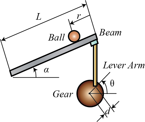
For this problem, we will ensure that the ball rolls without slipping and the friction between the beam and ball is negligible.
The constants and variables for this example are defined as follows:
(m) mass of the ball 0.11 kg
(R) radius of the ball 0.015 m
(d) lever arm offset 0.03 m
(g) gravitational acceleration 9.8 m/s^2
(L) length of the beam 1.0 m
(J) ball's moment of inertia 9.99e-6 kg.m^2
(r) ball position coordinate
(alpha) beam angle coordinate
(theta) servo gear angle
The design criteria for this problem are:
- Settling time less than 3 seconds
- Overshoot less than 5%
Create world frame and basic configuration
Open a new Simscape Multibody model by typing smnew in the MATLAB command window. A new model, as shown below, opens with a few commonly used blocks already in the model. The PS-Simulink and Simulink-PS blocks define the boundary between Simulink input/output models where the blocks are evaluated sequentially and Simscape models where the equations are evaluated simultaneously. Furthermore, you will need to define the associated model parameters in the MATLAB workspace. This can be accomplished by running the file ball_beam_properties.m which can be downloaded by right-clicking and selecting Save link as ....
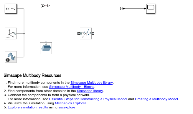
To configure basic settings in the model, carry out the following:
- Double-click on the Mechanism Configuration block and set Gravity to "[0 -9.81 0]", this represents an acceleration due to gravity of
 acting along the global -Y direction
- Open the Solver Configuration block and ensure that the Use local solver checkbox is not selected
- Type CTRL-E to open the Configuration Parameters dialog
- On the Solver pane, ensure that Type is set to "Variable-Step" and that Solver is set to "ode23t"
- Expand the section Solver details by clicking on the triangle
- Set Absolute tolerance to "1e-4"
Assemble the gear
The gear needs a pin at its center and another pin at a radial distance of d from the center where the lever is attached.
- Connect the B port of the Rigid Transform block to the W port of the World Frame.
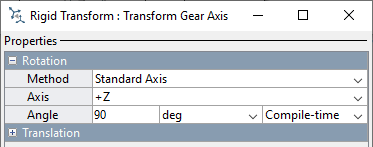
- Double-click on the Rigid Transform block
- In group Rotation, set Method to "Standard Axis", Axis to "+Z" and Angle to "90 deg"
- Rename the Rigid Transform block to "Transform Gear Axis"
Tips for adding blocks:
- Use Quick Insert to add the blocks. Click in the diagram and type the name of the block (use the letters in bold below). A list of blocks will appear and you can select the block you want from the list.
- After the block is entered, a prompt will appear for you to enter a parameter.
- To rotate a block or flip blocks, right-click on the block and select the desired option from the Rotate & Flip menu.
- To show the parameter below the block name, see Set Block Annotation Properties in the Simulink documentation.
Add the following blocks:
* Revolute Joint, rename this "Revolute Gear"
* Transfer Fcn
* Gain
* Step Input
Define the degree of freedom for the gear.
- Connect the B port of Revolute Gear to F port of Transform Gear Axis
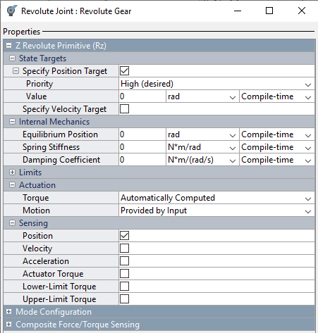
- Double-click on "Revolute Gear"
- In group Z Revolute Primitive (Rz) within State Targets, set the checkbox for Specify Position Target
- Set Priority to "High" and Value to "0 deg"
- In group Actuation, set Torque to "Automatically Computed"
- In group Actuation, set Motion to "Provided by Input"
- In group Sensing, set the checkbox for Position
Create a subsystem to define the gear and pins:
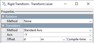
- Make a copy of Transform Gear Axis, rename the new block "Transform Lever"
- Connect the B port of Transform Lever to the F port of Revolute Gear
- Double-click on Transform Lever
- In group Rotation, set Method to "None"
- In group Translation, set Axis to "-Y", Offset to "d" with units of meters "m", then click OK
- Click on Transform Lever to select it
- Type CTRL-G to create a subsystem and name the subsystem "Gear"
Now we will add the pins:
- Double-click on the subsystem to enter it
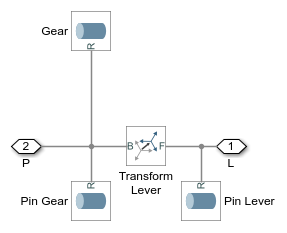
- Rename port 1 "P", and port 2 "L"
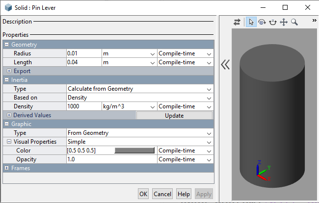
- Insert a Cylindrical Solid block (Solid block before R2019b)
- Rename the block "Pin Gear"
- Double-click on "Pin Gear"
- In releases prior to R2019b, set Shape to "Cylinder"
- In group Geometry, set Radius to "0.01 m" and Length to "0.02 m", then click OK
- Connect R port on Pin Gear to the B port of Transform Lever
- Copy and paste Pin Gear and name the new block "Pin Lever"
- Double-click "Pin Lever"
- In group Geometry, set Length to "0.04 m" and click OK
- Connect R port on Pin Lever to F port of Transform Lever
Now we will define the gear:
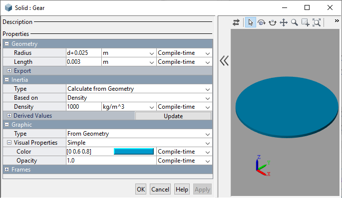
- Copy and paste Pin Gear and name the new block "Gear"
- Double-click on "Gear"
- In group Geometry, set Radius to "d+0.025 m" and Length to "0.003 m"
- In group the Graphic under Visual Properties, set Color to "[0 0.6 0.8]"
- Click OK
- Connect R port on Gear to B port of Transform Lever
Here is the Gear subsystem:
We will drive the gear with a motion input. The motion input must be filtered to avoid an algebraic loop. We must also ensure that the motion control signal and its first two derivatives are continuous, so we will apply a critically damped filter in the Simulink-PS converter block.
- Connect the Simulink-PS converter to the q input of Revolute Gear
- Double-click on the Simulink-PS converter and set Input signal unit to "rad"
- On the Input Handling tab, set Filtering and derivatives to "Filter input, derivatives calculated"
- On the Input Handling tab, set Input filtering order to "Second-order filtering"
- On the Input Handling tab, set Input filtering time constant to "0.01 seconds"
- Connect the output of Transfer Fcn to the Simulink-PS Converter
- Double-click Transfer Fcn and set Denominator coefficients to "[0.01 1]"
- Connect Step to the input of Transfer Fcn and name that signal "Gear Angle"
- Double-click the Step block and set Final value to "0.3"
We will measure the angle of the gear and use that angle to estimate the angle of the beam upon which the ball is resting.
- Connect the PS-Simulink Converter to the q output of Revolute Gear
- Drop the Gain block on a straight section of the signal connecting the PS-Simulink Converter to the Scope
- Double-click on the Gain block and set Gain to "d/L"
- Double-click on the input signal for the Scope and name it "Approx" as this is the approximate value for the angle of the beam
The overall model will look like the following:
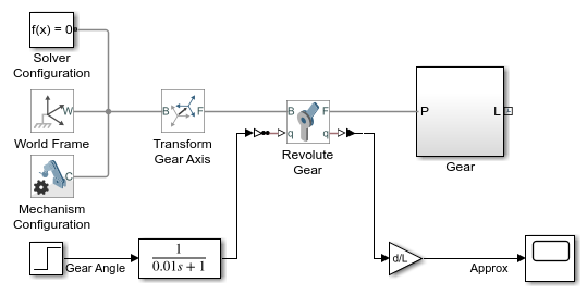
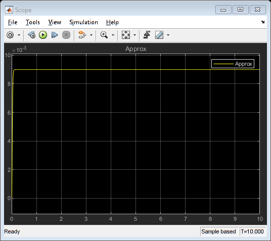
Running the simulation (CTRL-T or press the green arrow run button) will produce the following plot.
Add the lever
For the given dimensions of the Gear and the Beam the lever that connects Gear and the beam needs to be 0.35 m in length. In this section we will add the lever to the model. Add the following items to the model:
- Add a Revolute Joint, rename it "Revolute Gear Lever"
- Connect B port of Revolute Gear Lever to L port of Gear subsystem
- Add a Rigid Transform block, rename it "Transform Center"
- Connect B port of Transform Center to F port of Revolute Gear Lever
- Click once on Transform Center to select it
- Press CTRL-G to create a subsystem and name it "Lever"
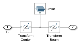
We will define a lever with one solid and two connection points. First we define the connection points.
- Double-click to enter the Lever subsystem
- Rename port 1 "B" and port 2 "F"
- Double-click on Transform Center
- In group Translation, set Axis to "+X", and set Offset to "0.35/2"
- Copy and paste Transform Center and name the new block "Transform Beam"
- Insert Transform Beam on the line between Transform Center and port F
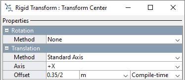
Now we define the lever
- Insert a Brick solid block (Solid block in releases before R2019b)
- Double-click on Brick Solid block
- In group Geometry, set Dimensions to "[0.35 0.03 0.01] m"
- In group Inertia, set Density to "7200 kg/m^3"
- In group Graphic under Visual Properties, set Color to "[1 0 0]"
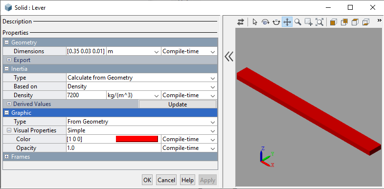
The Lever subsystem should look like the following:
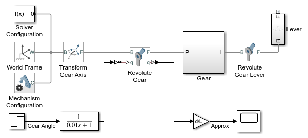
The whole model should appear as follows:
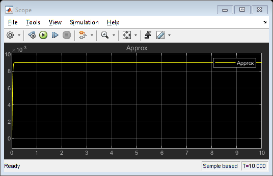
Simulating the model shows the results as the lever swings around:
Add the beam
We will now define the connection between the beam and lever.
- Copy and paste Revolute Gear Lever, rename the new block "Revolute Lever Beam"
- Connect B port of Revolute Lever Beam to F port of Lever subsystem
- Add a Rigid Transform, rename the new block "Transform Lever"
- Connect B port of Transform Lever to F port of Revolute Lever Beam
- Click once on Transform Lever to select it
- Press CTRL-G to create a subsystem and name it "Beam"
We will define the beam inside this subsystem. First we define the connection points for the end of the beam.
- Double-click on subsystem "Beam"
- Rename the port connected to Revolute Lever Beam to "L", this should be the port connected to port B of Transform Lever
- Rename the other port "P"
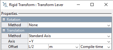
- Double-click on Transform Lever
- In group Translation, set Method to "Standard Axis"
- In group Translation, set Axis to "+Ý" and Offset to "L/2"
- Copy and paste Transform Leve, name the new block "Transform Beam Center"
Next we define the beam.
- Add a Brick Solid block to this subsystem (Solid block prior to R2019b), name this new block "Beam"
- Double-click on Beam
- In releases prior to R2019b, set Shape to "Brick"
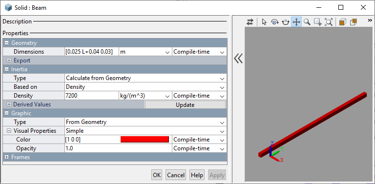
- In group Geometry, set Dimensions to "[0.025 L+0.04 0.03] m"
- In group Inertia, set Density to "7200 kg/m^3"
- In group Graphic under Visual Properties, set Color to "[1 0 0]"
We will define pins to visually represent the connection between the beam and the lever and a fixed point in space.
- In the Beam subsystem, add a Cylindrical Solid block (Solid block prior to R2019b). Name the new block "Pin Beam Pivot".
- Double-click on Pin Beam Pivot
- In releases prior to R2019b, set Shape to "Cylindrical"
- In group Geometry, set Radius to "0.01 m"
- In group Geometry, set Length to "0.04 m" and click OK
- Connect R port of Pin Beam Pivot to Transform Beam Center port B
- Copy and paste Pin Beam Pivot, name the new block "Pin Lever Beam"
- Connect R port of Pin Lever Beam to B port of Transform Lever
Now we define the reference frame for the ball.
- In subsystem Beam, add a Rigid Transform block and name the new block "Transform Beam End Ball"
- In group Rotation, set Method to "Aligned Axes"
- In group Rotation, under Pair 1, set Follower to "+Z" and set Base to "+Y"
- In group Rotation, under Pair 2, set Follower to "+Y" and set Base to "+X"
- In group Translation, set Method to "Standard Axis"
- In group Translation, set Axis to "+X" and Offset to "0.025/2 m"
- Connect B port of Transform Beam End Ball to Transform Lever B port
- Copy and paste port P and name the new port B.
- Connect Port B to Transform Beam End Ball port F

The Beam subsystem should like the following:
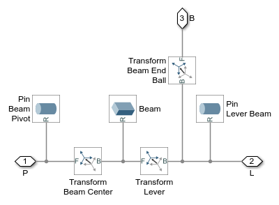
Now ee need to define the connection between the beam and a fixed point in space.
- Add a Rigid Transform block, name the new block "Transform Beam Pivot"
- Connect the B port of Transform Beam Pivot to World Frame
- Copy and paste Revolute Gear and name the new block "Revolute Beam"
- Double-click on Revolute Beam
- In group Sensing, uncheck the box for Position
- Connect the B port of Revolute Beam to Transform Beam Pivot F port
- Connect the F port of Revolute Beam to P port of Beam subsystem
- Copy and paste the PS-Simulink block connected to Revolute Gear
- Connect q port of Revolute Beam to the new PS-Simulink block
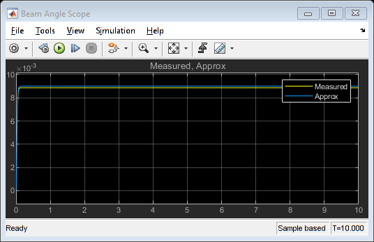
- Connect the output of the PS-Simulink block to the Scope and name the new signal "Measured"
The whole model should then appear as follows:

Simulating the model then produces the following plot as the lever swings around.
Add the ball
Now we will add the ball to our model. The ball must be constrained to translate along the beam, and a separate constraint is used to ensure that the ball rolls without slipping on the beam. A few blocks are used to define the axes and constraints.
- Add Rack and Pinion Constraint block
- Connect the F port to the B port of subsystem Beam
- Click once on the Rack and Pinion Constraint block to select it
- Press CTRL-G to create a subsystem
- Rename the subsystem "Ball Beam Constraints"
Inside this subsystem, we will define the constraints for the ball. First we will define the constraint for rolling without slipping.
- Double-click subsystem Ball Beam Constraints to enter it
- Rename the port connected to the F port of rack and Pinion Constraint to "Beam"
- Rename the other port "Ball"
- Double-click on Rack and Pinion Constraint and set parameter Pinion Radius to "R m"
Next, we will add the constraint for the ball to translate along the beam.
- Add a Prismatic Joint to the model
- Double-click on Prismatic Joint
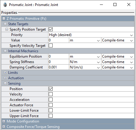
- In group Z Prismatic Primitive (Pz), under State Targets, set the checkbox for Specify Position Target
- Set Priority to "High", and set Value to "0"
- In group Internal Mechanics, set Damping Coefficient to "0.001 N/(m/s)"
- In group Sensing, set the checkbox for Position
Connect the Prismatic Joint to the reference frame and sense the ball position.
- Connect the B port to the F port of Rack and Pinion Constraint
- Add a PS-Simulink converter block
- Connect the PS-Simulink converter block to the p port of Prismatic Joint
- Double-click the PS-Simulink converter block and set Output signal unit to "m"
- Add an output signal port and name that new port "x"
- Connect the PS-Simulink converter block to the output
We need to add a degree of freedom so that the ball can rotate as it rolls. We first need to define the axis of rotation.
- Add a Rigid Transform block and name that block "Transform Pinion"
- Double-click the block Transform Pinion
- In group Rotation, set Method to "Standard Axis"
- In group Rotation, set Axis to "+Y" and Angle to "90 degrees"
- In group Translation, set Method to "Standard Axis"
- In group Rotation, set Axis to "+Y", Offset to "R meters"
- Connect B port of Transform Pinion to Prismatic Joint F port
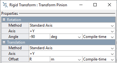
Now we can add the degree of freedom.
- Add a Revolute Joint
- Connect the F port of the Revolute Joint to the B port of the Rack and Pinion Constraint
- Connect the B port of the Revolute Joint to the F port of Transform Pinion
The Ball Beam Constraints subsystem should look like the following:
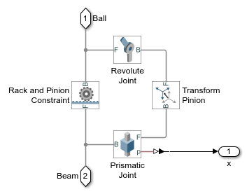
Finally, we can add the ball.
- Navigate to the top level of the model
- Add a Spherical Solid block (Solid block prior to R2019b)
- Name this block "Ball"
- Double-click block "Ball"
- In releases prior to R2019b, set Shape to "Sphere"
- In group Geometry set Radius to "R meters"
- In group Inertia set Type to "Custom"
- In group Inertia set Moments of Inertia to "[J J J] kg*m^2"
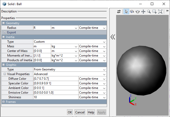
- Connect R port of Ball to Ball port of subsystem Ball Beam Constraints
- Add a Scope block and connect port x of Ball Beam Constraints to the new Scope, name that signal "x Ball"
The resulting complete model should look something like the following:
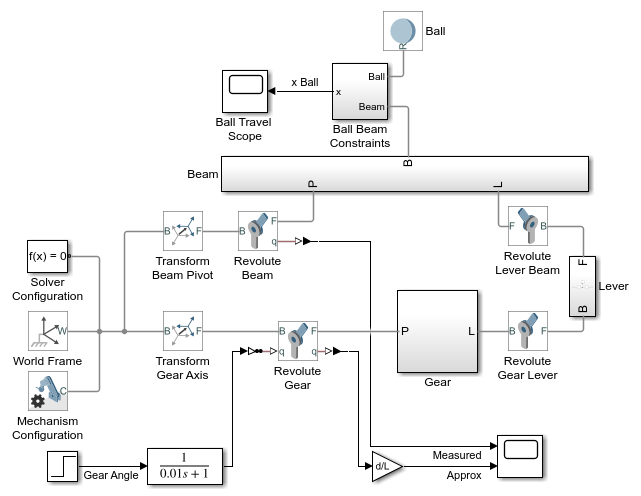
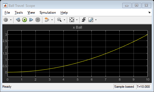
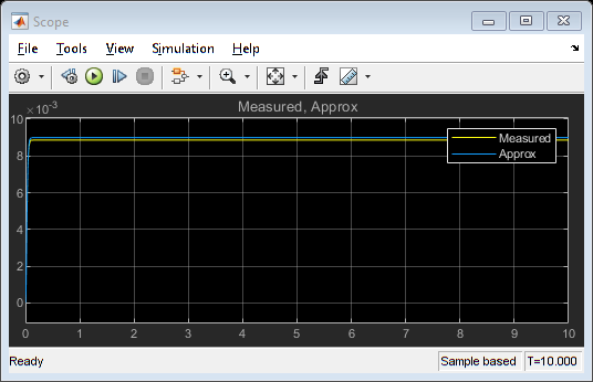
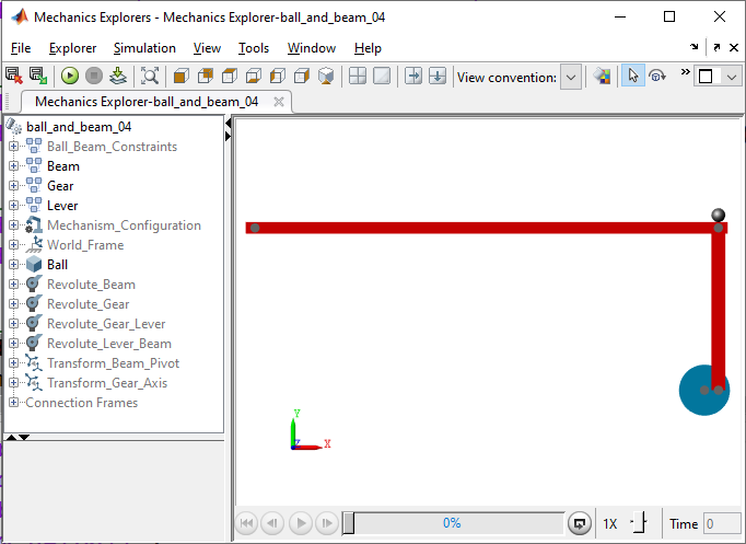
If you simulate this system, you should then see the following response from the scopes. As well as the following animation.
Implementing the controller
We have now successfully modeled the physical system. We will convert this into a subsystem and add the controller.
- Click once in the diagram (but not on a block) and press CTRL-A to select all blocks
- Hold the Shift key and click on the Step block and the Scope to unselect those blocks
- Press CTRL-G to create a subsystem
- Rename the subsystem "Ball on Beam"
Now we will close the loop with a controller.
- Delete the connection between the Step block and the Ball on Beam subsystem
- Add a Gain block and set parameter Gain to "pi/180"
- Connect the output of the Gain to the input of Ball on Beam subsystem
- Add a Transfer Fcn block and name the block "Lead Compensator"
- Double-click on Lead Compensator
- Set parameter Numerator coefficients to "[1 0.01]"
- Set parameter Denominator coefficients to "[1 5]"
- Connect the output of Lead Compensator to the Gain block
- Copy and paste the Gain block and change the Gain of the new block to "37.1"
- Add a Subtract block
- Connect the output of the Subtract block to the Lead Compensator
- Connect the Step block to the + port of the Subtract block and change the name of the Step block to "Target Ball Position"
- Connect Ball on Beam output "x Ball" to the - port of the Subtract block
- Connect Target Ball Position to the Scope
As this is now a stiff system, we need to change the solver settings.
- Type CTRL-E to open the Configuration Parameters dialog.
- On the Solver pane, set Solver to "ode23t"
- Change Stop time to "1000"
The resulting closed-loop system should appears as follows:

Running the simulation then produces the following outputs as observed on the Scope.
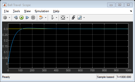
You can download the final Simscape model created here by right-clicking here and then selecting Save link as ....


