


DC Motor Position: Simscape Modeling
Contents
Physical setup
In this section, we show how to build the DC Motor model using the physical modeling blocks of the Simscape extension to Simulink. The blocks in the Simscape library represent actual physical components; therefore, complex multi-domain models can be built without the need to build mathematical equations from physical principles as was done previously by applying Newton's laws and Kirchoff's laws to generate the model implemented in DC Motor Position: Simulink Modeling.
The following figure shows a schematic of the DC Motor system we will be modeling in this page.
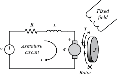
The system parameters are as follows:
(R) Armature Resistance 4 ohms
(L) Armature Inductance 2.75E-6 H
(K) Torque Constant/Back emf Constant 0.0274 Nm/A or Vs/rad
(J) Rotor Inertia 3.2284E-6 kg.m^2
(b) Rotor damping 3.5077E-6 Nms/rad
Open a new Simscape model by typing ssc_new in the MATLAB command window. A new model, as shown below, will open with a few commonly used blocks already in the model. The PS-Simulink and Simulink-PS blocks define the boundary between Simulink input/output models where the blocks are evaluated sequentially and Simscape models where the equations are evaluated simultaneously.

Create the motor model
To create the motor model a number of blocks have to be added to the model.
Tips for adding blocks:
- Use Quick Insert to add the blocks. Click in the diagram and type the name of the block (use the letters in bold below). A list of blocks will appear and you can select the block you want from the list.
- After the block is entered, a prompt will appear for you to enter the parameter. Enter the variable names as shown below.
- To rotate a block or flip blocks, right-click on the block and select the desired option from the Rotate & Flip menu.
- To show the parameter below the block name, see Set Block Annotation Properties in the Simulink documentation
Add the following blocks:
* DC Motor block
* Current Sensor block (be sure to get the one
from the Foundation Library)
* Controlled Voltage Source block (be sure to get the one
from the Foundation Library)
* Electrical Reference block (be sure to get the one
from the Foundation Library)
* Ideal Rotational Motion Sensor block
* Mechanical Rotational Reference block
* Step
The DC Motor block models both the electrical and mechanical characteristics of the motor.
- Double-click on the DC Motor block and ensure Model parameterization is set to "By equivalent circuit parameters"
- Set Armature resistance to "4 Ohm"
- Set Armature inductance to "2.75E-6 H"
- Set Define back-emf or torque constant to "Specify back-emf constant"
- Set Back-emf constant to "0.0274 V/(rad/s)"
- On the Mechanical tab, set Rotor inertia to "3.2284E-6 kg*m^2" and Rotor damping to "3.5077E-6 N*m/(rad/s)"
Note that since the motor torque constant and the back emf constant are equal if the units are consistent, we only need to define one of the two.
We need to measure the position, speed, and current drawn by the motor.
- Connect the R port of the Ideal Rotational Motion Sensor to the R port of the DC Motor
- Connect the C port of the DC Motor to the Mechanical Rotational Reference
- Connect the C port of the Ideal Rotational Motion Sensor to the Mechanical Rotational Reference
- Connect the - port of the Current Sensor to the + port of the DC Motor
- Connect the + port of the Current Sensor to the + port of the Controlled Voltage Source
- Connect the - port of the Controlled Voltage Source to the Electrical Reference
- Connect the - port of the DC Motor to the Electrical Reference
Next, we have to connect the input signals and measurements to the input and output blocks. This will let us control the motor using Simulink.
- Connect the Simulink-PS block to the Controlled Voltage Source input
- Double-click that signal connection and set the signal name to "Voltage"
- Double-click on the Simulink-PS block and set Input signal units to "V"
- Connect the Step block to the Simulink-PS block
- Double-click on the Step block and set Step time to "0"
- Connect the A port of the Ideal Rotational Motion Sensor block to the PS-Simulink block (already in the diagram, connected to a Scope)
- Double-click on the signal connected to the Scope and set the signal name to "Position"
- Make two additional copies of the PS-Simulink block (you need 3 total)
- Double-click on the original PS-Simulink block and set the Output signal units to "rad"
- Connect Current Sensor to a PS-Simulink block, then double-click on that PS-Simulink block and set Output signal units to "A"
- Connect the W port of the Ideal Rotational Motion Sensor block to a PS-Simulink block, then double-click on that PS-Simulink block and set Output signal units to "rad/s"
- Copy and paste the Scope block
- Connect the PS-Simulink outputs for the current and speed signals to the Scope and name the signals "Current" and "Speed"
The Solver Configuration block defines how the equations of a Simscape network are handled. Connect it to any electrical connection. We do not need to modify the parameters; we will use the defaults.
Delete any other unconnected items in the block diagram.
- Type CTRL-E to open the Configuration Parameters dialog
- On the Solver pane, ensure that Type is set to "Variable-Step" and that Solver is set to "auto", also set the Stop time to "0.1"
The resulting model should appear as follows.

Running the simulation (CTRL-T or press the green arrow run button) will produce the following plot.

Create a subsystem
We will now place the motor into a subsystem.
- Click once in the diagram (but not on a block) and press CTRL-A to select all blocks
- Hold the Shift key and click on the Step block and the Scope for the Speed signal to unselect those blocks
- Press CTRL-G to create a subsystem
- Rename the subsystem "Motor Model Subsystem"

Set up the controller
In the DC Motor Position: Digital Controller Design page a digital controller was designed. We will use the same controller to simulate the associated closed-loop control system with the Simscape model of the DC motor plant.
Add the following blocks to the system:
- Zero Order Hold block
- Discrete Zero Pole block
- Subtract block
Make these changes to add the digital controller:
- Drop the Zero-Order Hold block on the line that is connected to the input of the Motor Model Subsystem
- Double-click on the Zero-Oder Hold block and set Sample Time to "0.001"
- Copy and paste the Zero-Order Hold block (right-click, drag, and drop)
- Drop the new Zero-Order Hold block on the output signal of the Motor Model Subsystem
- Drop the Discrete Zero Pole block on the signal between the Step input and the first Zero-Order Hold block
- Delete the line that connects the Step block to the Discrete Zero Pole block
- Connect the output of the Subtract block to the input of the Discrete Zero Pole block
- Connect the Step block to the + port of the Subtract block
- Connect the output of the Zero-Order hold block on the output signal of the Motor Model Subsystem to the - port of the Subtract block
- Connect the output of the Step block to the Scope
Check your connections against the screenshot below.

When the connections are correct, set the parameters for the discrete controller as follows:
- Double-click on the Discrete Zero Pole block
- Set the Zeros field to "[0.95 0.80 0.80]"
- Set the the Poles field to "[-0.98 0.6 1]"
- Set the Sample time field to "0.001"
- Change the name to "Controller"
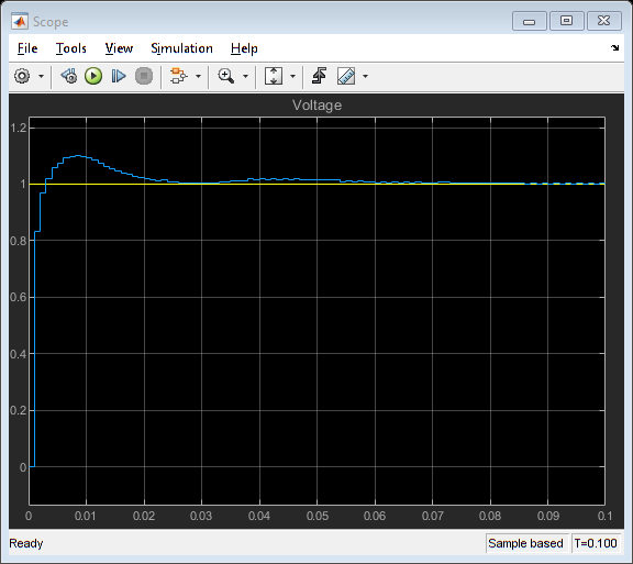
Then run the simulation (press CTRL-T or press the green arrow run button). From the simulation results, it appears that the overshoot is less than 16% and the settling time is less than 0.04 seconds as required. This is consistent with the analysis employed in designing the digital controller.

Effect of a constant disturbance
We will try to assess the response of the system with a disturbance present. A step disturbance can be added in a similar manner to how the step reference was added.
- Delete the connection between the Zero Order Hold and the Motor Model Subsystem input
- Add a Sum block to the diagram
- Connect the Sum block between the Zero-Order Hold and the input to Motor Model Subsystem.
- Copy and paste the Step block and rename that block "Disturbance"
- Connect the output port of "Disturbance" to the Sum block
- Double-click on Disturbance and set Step time to "0.03"
Your model should now appear as follows.
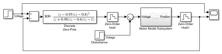
Running the simulation produces the plot shown below. From inspection of the results, you can see that there is a slight bump beginning at 0.03 seconds due to the disturbance, but the system is able to reject its effect and the steady-state error still goes to zero as required.
You can download the final Simscape model created here by right-clicking here and then selecting Save link as ....
