Extras: Digital Steady-State Error
Contents
For a continuous-time system design, we often use the Final Value Theorem
(1)
to find the steady-state error for a given system and input. Recall that this theorem only holds if the poles of  have negative real part. There is also a version of the Final Value Theorem for discrete-time systems. The discrete version
of the Final Value Theorem is defined as follows
(2)
where it is necessary that all poles of  are inside the unit circle.
For example, suppose we have the following discrete transfer function.
(3)
First, let's obtain the poles of this transfer function and see if they are located inside the unit circle. We can find the poles by hand or by employing the following MATLAB commands.
z = tf('z',-1);
sys_d = (z + 0.5)/(z^2 - 0.6*z + 0.3);
[p,z] = pzmap(sys_d)
p =
   0.3000 + 0.4583i
   0.3000 - 0.4583i
z =
   -0.5000
Since both poles are inside the unit circle, the Final Value Theorem will hold.
Finding steady-state error to the unit step input
Let the input  be the unit step input as shown below.
(4)
The output  then is the following.
(5)
Applying the Final Value Theorem yields the following.
(6)
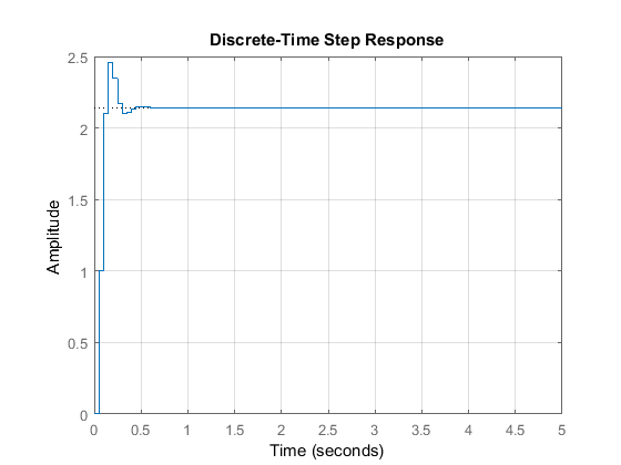
Therefore, the steady-state output of the above discrete-time system to a unit step input is 2.14. This corresponds to a steady-state error of 114%.
Let's confirm this by obtaining a step response plot of the system. Create a new m-file and enter the following commands. Running this m-file in the command window generates the step response shown below.
Ts = .05;
z = tf('z',Ts);
sys_d = (z + 0.5)/(z^2 - 0.6*z + 0.3);

step(sys_d,5);
grid
title('Discrete-Time Step Response')

The steady-state value is 2.14 as we expected.
Finding steady-state error to the impulse input
Now change the input  from a unit step to a unit impulse.
(7)
Applying the Final Value Theorem again yields the following.
(8)
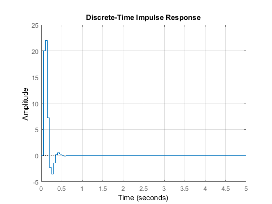
Therefore, the steady-state output of the above system to a unit impulse input is 0.
Change the step command in the above m-file to the impulse command and rerun it in the MATLAB command window. You should see the following response.
Ts = .05;
z = tf('z',Ts);
sys_d = (z + 0.5)/(z^2 - 0.6*z + 0.3);

impulse(sys_d,5);
grid
title('Discrete-Time Impulse Response')

From this plot we see that the steady-state output to a unit impulse input is 0 as was predicted.


